


Jharkhand
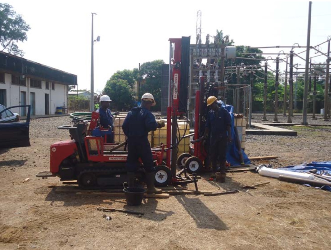
Pile Foundation of all types of 220KV Multi...

Scope of Work :
Our scope of work was to deliver the following design and drawings and obtaining approval from BSPTCL :
| SL. NO. | DESCRIPTION | SIZE | QNTY | UNIT | |
| Hathua | Bhorey | ||||
| A. | ELECTRICAL DRAWINGS : | ||||
| 1 | SLD | ||||
| 1.1 | Key SLD - 132/33kV Substation | A2 | 1 | NO. | |
| 1.2 | Key SLD - 132kV Extension Substation | A3 | 1 | NO. | |
| 1.3 | 132/33kV Switchyard - Protection & metering SLD | A1 | 1 | NO. | |
| 1.4 | 132kV Extension Switchyard - Protection & metering SLD | A3 | 1 | NO. | |
| 1.5 | SLD - 415V Main Switchboard | A3 | 1 | NO. | |
| 1.6 | SLD - 415V ACDB | A2 | 1 | NO. | |
| 1.7 | SLD - 415V MLDB | A3 | 1 | NO. | |
| 1.8 | SLD - 415V Emergency LDB | A4 | 1 | NO. | |
| 1.9 | SLD - 415V Power distribution for Air conditioning system | A4 | 1 | NO. | |
| 1.10 | SLD - 220V DCDB | A3 | 1 | NO. | |
| 1.11 | SLD - 48V DCDB | A3 | 1 | NO. | |
| 1.12 | SLD - ACDB & DCDB for 132kV Extension Switchyard | A2 | 1 | NO. | |
| 1.13 | SLD - Bay Marshalling Kiosk - 132kV | A3 | 1 | NO. | |
| 1.14 | SLD - Bay Marshalling Kiosk - 33kV | A3 | 1 | NO. | |
| 2 | ELECTRICAL LAYOUT & ELEVATION, EKD | ||||
| 2.1 | Land Utilization Plan - 132/33kV Substation | A0 | 1 | NO. | |
| 2.2 | Switchyard Layout - Plan and Elevation of 132/33kV Switchyard | A0 | 1 | NO. | |
| 2.3 | Switchyard Layout - Plan and Elevation of 132kV Extension Switchyard | A2 | 1 | NO. | |
| 2.4 | Erection key diagram - Plan and Elevation of 132/33kV Switchyard | A0 | 1 | NO. | |
| 2.5 | Erection key diagram - Plan and Elevation of 132kV Extension Switchyard | A2 | 1 | NO. | |
| 2.6 | Electrical Equipment Layout with cable trench details - Control Building of 132/33kV Switchyard | A2 | 1 | NO. | |
| 2.7 | Electrical Equipment Layout with cable trench details - Control Building of 132kV Extension Switchyard | A3 | 1 | NO. | |
| 3 | CABLE ROUTING, TRAY & TRENCH LAYOUT AND DETAILS | ||||
| 3.1 | Switchyard Cable trench layout and sections with BOM of cable trays of 132/33kV Switchyard | A1 | 1 | NO. | |
| 3.2 | Switchyard Cable trench layout and sections with BOM of cable trays of 132kV Extension Switchyard | A3 | 1 | NO. | |
| 4 | EARTHING LAYOUT & DETAILS | ||||
| 4.1 | Earthing layout & BOM of 132/33kV Switchyard | A1 | 1 | NO. | |
| 4.2 | Earthing layout & BOM of 132kV Extension Switchyard | A3 | 1 | NO. | |
| 4.3 | Earthing layout - Control building | A2 | 1 | NO. | |
| 4.4 | Earthing and Lightning protection layout - DG room | A3 | 1 | NO. | |
| 4.5 | Typical Earthing system installation details | A4 | 28 | NOS. | |
| 5 | LIGHTNING PROTECTION LAYOUT & DETAILS | ||||
| 5.1 | DSLP layout and BOM of 132/33kV Switchyard | A0 | 1 | NO. | |
| 5.2 | DSLP layout and BOM of 132kV Extension Switchyard | A3 | 1 | NO. | |
| 5.3 | Lightning protection layout with BOM for Control Building | A3 | 1 | NO. | |
| 6 | ILLUMINATION AND SMALL POWER LAYOUT | ||||
| 6.1 | Illumination layout, SLD and BOM - Switchyard and Road of 132/33kV Switchyard | A0 | 1 | NO. | |
| 6.2 | Illumination layout, SLD and BOM - 132kV Extension Switchyard | A3 | 1 | NO. | |
| 6.3 | Illumination and small power layout, SLD and BOM - Control building | A1 | 1 | NO. | |
| 6.4 | Illumination and small power layout, SLD and BOM - Store shed | A3 | 1 | NO. | |
| 6.5 | Illumination and small power layout, SLD and BOM - DG shed | A4 | 1 | NO. | |
| 6.6 | Illumination and small power layout, SLD and BOM - Pump house for water distribution | A4 | 1 | NO. | |
| 6.7 | Deleted | ||||
| 6.8 | Illumination and small power layout, SLD and BOM - Officer quarter (3BHK) | A1 | 1 | NO. | |
| 6.9 | Illumination and small power layout, SLD and BOM - Staff quarter (2BHK) | A0 | 1 | NO. | |
| 6.10 | Illumination and small power layout, SLD and BOM - Dormitory building | A3 | 1 | NO. | |
| 6.11 | Conduit Layouts | A1 | 3 | NOS. | |
| A3 | 2 | NO. | |||
| 7 | CONTROL SCHEMATICS & BLOCK DIAGRAMS | ||||
| 7.1 | BMK control terminal plan for 132kV Switchyard | A2 | 1 | NO. | |
| 7.2 | BMK control terminal plan for 33kV Switchyard | A2 | 1 | NO. | |
| 8 | CABLE SCHEDULE & INTERCONNECTION DIAGRAMS | ||||
| 8.1 | 132kV switchyard - Control Cable schedule and Interconnection Diagrams | A4 | 1 | LOT | |
| 8.2 | 33kV switchyard - Control Cable schedule and Interconnection Diagrams | A4 | 1 | LOT | |
| 8.3 | LV Switchgear, ACDB, DCDB, MLDB, ELDB, SLDBs, BMK - Power Cable Schedule and Interconnection Diagram | A4 | 1 | LOT | |
| 8.4 | 132kV Extension Switchyard - Control Cable schedule and Interconnection Diagrams | A4 | 1 | LOT | |
| 8.5 | 132kV Extension Switchyard - Power Cable Schedule and Interconnection Diagram | A4 | 1 | LOT | |
| 9 | CCTV SYSTEM | ||||
| 9.1 | CCTV Layout drawing and BOQ | A1 | 1 | NO. | |
| B. | ELECTRICAL DESIGN CALCULATIONS | ||||
| 1 | 132/33kV Switchyard - Earthing calculation | A4 | 1 | LOT | |
| 2 | 132/33kV Switchyard DSLP calculation | A4 | 1 | LOT | |
| 3 | 132/kV Extension Switchyard DSLP calculation | A4 | 1 | LOT | |
| 4 | Lighting calculation - Control Building | A4 | 1 | LOT | |
| 5 | Lighting calculation - 132/33kV switchyard | A4 | 1 | LOT | |
| 6 | Lighting calculation - Switchyard roads | A4 | 1 | LOT | |
| 7 | Lighting calculation - DG Room | A4 | 1 | LOT | |
| 8 | Lighting calculation - Store shed | A4 | 1 | LOT | |
| 9 | Lighting calculation - Pump house | A4 | 1 | LOT | |
| 10 | Lighting calculation - Security room | A4 | 1 | LOT | |
| 11 | Lighting calculation - Officer quarter | A4 | 1 | LOT | |
| 12 | Lighting calculation - Staff quarter | A4 | 1 | LOT | |
| 13 | Lighting calculation - Dormatory building | A4 | 1 | LOT | |
| 14 | Sag & Tension Calculation of Strung Bus Conductor | A4 | 1 | LOT | |
| 15 | Short Circuit Force Calculation of Strung Bus Conductor | A4 | 1 | LOT | |
| 16 | Short Circuit Force Calculation of Rigid Bus Conductor | A4 | 1 | LOT | |
| C. | STRUCTURAL DRAWINGS WITH BOM AND WEIGHT AND DESIGN CALCULATIONS : | ||||
| C.1 | 132KV : | ||||
| 1 | Structural GA drawing of 132kV Line gantry tower | A1 | 1 | NO. | |
| 2 | Structural GA drawing of 132kV Line gantry beam | A2 | 1 | NO. | |
| 3 | Structural GA drawing of 132kV Transformer gantry tower | A1 | 1 | NO. | |
| 4 | Structural GA drawing of 132kV Transformer gantry beam | A2 | 1 | NO. | |
| 5 | Structural GA drawing of 132kV Main bus A-Frame structure | A2 | 1 | NO. | |
| 6 | Structural GA drawing of 132kV Transfer bus A-Frame structure | A2 | 1 | NO. | |
| 7 | Structural GA drawing of 132kV Main bus A-Frame structure with 132kV Bus Section Isolator | A2 | 1 | NO. | |
| 8 | Structural GA drawing of pipe type support structure for 132kV Isolator with/without E/S, Tandem Isolator, LA, CVT, CT, BPI, PT | A1 | 2 | NOS. | |
| 9 | Deleted | ||||
| 10 | Structural GA drawing of 132kV Line gantry tower for 132kV Extension Switchyard | A1 | 1 | NO. | |
| 11 | Structural GA drawing of 132kV Line gantry beam for 132kV Extension Switchyard | A2 | 1 | NO. | |
| 12 | Structural GA drawing of 132kV Bus gantry tower for 132kV Extension Switchyard | A1 | 1 | NO. | |
| 13 | Structural GA drawing of 132kV Bus gantry beam for 132kV Extension Switchyard | A2 | 1 | NO. | |
| 14 | |||||
| 15 | Structural GA drawing of lattice type support structure for 132kV Isolator with/without E/S, Tandem Isolator, LA, CVT, CT, BPI | A1 | 2 | NOS. | |
| C.2 | 33KV : | ||||
| 1 | Structural GA drawing of 33kV Line gantry tower | A2 | 1 | NO. | |
| 2 | Structural GA drawing of 33kV Line gantry beam | A3 | 1 | NO. | |
| 3 | Structural GA drawing of 33kV Transformer gantry tower | A2 | 1 | NO. | |
| 4 | Structural GA drawing of 33kV Transformer gantry beam | A3 | 1 | NO. | |
| 5 | Structural GA drawing of 33kV Main bus A-Frame structure | A3 | 1 | NO. | |
| 6 | Structural GA drawing of 33kV Transfer bus A-Frame structure | A3 | 1 | NO. | |
| 7 | Structural GA drawing of 33kV Main bus A-Frame structure with 33kV Bus Section Isolator | A3 | 1 | NO. | |
| 8 | Structural GA drawing of pipe type support structure for 33kV Isolator with/without E/S, Tandem Isolator, LA, PT, CT, BPI, HG Fuse | A1 | 2 | NOS. | |
| C.3 | STRUCTURAL DESIGN CALCULATIONS : | ||||
| 1 | Structural design calculations - 132kV | A4 | 1 | LOT | |
| 2 | Structural design calculations - 33kV | A4 | 1 | LOT | |
| D. | CIVIL CONSTRUCTIONAL DRAWINGS AND DESIGN CALCULATIONS : | ||||
| D.1 | GENERAL : | ||||
| 1 | Overall foundation layout of 132/33kV switchyard | A1 | 1 | NO. | |
| 2 | Overall foundation layout of 132kV extension switchyard | A3 | 1 | NO. | |
| 3 | Foundation details of Lightning mast | A3 | 1 | NO. | |
| 4 | Foundation design calculations for lightning mast | A4 | 1 | LOT | |
| D.2 | 132KV GANTRY TOWER AND EQUIPMENT FOUNDATION DETAILS : | ||||
| 1 | Foundation details of 132kV Line gantry tower | A3 | 1 | NO. | |
| 2 | Foundation details of 132kV Transformer gantry tower | A3 | 1 | NO. | |
| 3 | Foundation details of A Frame - 132kV Main bus | A3 | 1 | NO. | |
| 4 | Foundation details of A Frame - 132kV Transfer bus | A3 | 1 | NO. | |
| 5 | Foundation details of A Frame - 132kV Main bus with 132kV Isolator | A3 | 1 | NO. | |
| 6 | Foundation details of support structure for 132kV Isolator with and without E/S, Tandem Isolator, LA, CVT, CT, BPI, PT, CB | A1 | 2 | NOS. | |
| 7 | Foundation details of 132kV Line gantry tower for 132kV Extension Switchyard | A3 | 1 | NO. | |
| 8 | Foundation details of 132kV Bus gantry tower for 132kV Extension Switchyard | A3 | 1 | NO. | |
| 9 | Foundation details of support structure for 132kV Isolator with and without E/S, Tandem Isolator, LA, CVT, CT, BPI, CB at 132kV Extension Switchyard | A1 | 2 | NOS. | |
| 10 | Foundation design calculations | A4 | 1 | LOT | |
| D.3 | 33KV GANTRY TOWER AND EQUIPMENT FOUNDATION DETAILS : | ||||
| 1 | Foundation details of 33kV Line gantry tower | A3 | 1 | NO. | |
| 2 | Foundation details of 33kV Transformer gantry tower | A3 | 1 | NO. | |
| 3 | Foundation details of A Frame - 33kV Main bus | A3 | 1 | NO. | |
| 4 | Foundation details of A Frame - 33kV Transfer bus | A3 | 1 | NO. | |
| 5 | Foundation details of A Frame - 33kV Main bus with 132kV Isolator | A3 | 1 | NO. | |
| 6 | Foundation details of support structure for 33kV Isolator with and without E/S, Tandem Isolator, LA, VT, CT, CB, BPI, HGF | A1 | 2 | NOS. | |
| 7 | Foundation design calculations | A4 | 1 | LOT | |
| D.4 | CIVIL CONSTRUCTIONAL DETAILS AND ARCHITECTURAL DETAILS OF CONTROL BUILDING: | ||||
| 1 | Architectural layout plan, elevation and details for Control building | A1 | 1 | NO. | |
| 2 | Control Building - GA of Foundation, Column RC Details | A1 | 1 | NO. | |
| 3 | GA of Control Building Plinth Beam Layout and Details | A2 | 1 | NO. | |
| 4 | Control Building - 1st floor Beam layout and Details | A2 | 1 | NO. | |
| 5 | Control Building - RC Details of1st floor Slab | A2 | 1 | NO. | |
| 6 | Control Building - Roof Beam layout and Details | A2 | 1 | NO. | |
| 7 | Control Building - RC Details of Roof Slab | A2 | 1 | NO. | |
| 8 | Control Building - Layout and RC Details of Lintel Beams, stair case & Miscellaneous Details | A2 | 1 | NO. | |
| 9 | Control Building - Indoor Cable Trenches RC details | A2 | 1 | NO. | |
| 10 | Constructional details of septic tank and soak pit | A2 | 1 | NO. | |
| 11 | Sanitary and plumbing details | A2 | 1 | NO. | |
| 12 | RCC Design calculations for Control building | A4 | 1 | LOT | |
| 13 | Design calculation for septic tank and soak pit | A4 | 1 | LOT | |
| D.5 | OFFICER'S QUARTER (3 BHK) : | ||||
| 1 | Architectural layout plan & elevation | A1 | 1 | NO. | |
| 2 | Civil drawings of foundation, column, plinth beam, roof beam, roof slab, lintel beam, mumty room etc. as per TS | A1 | 6 | NOS. | |
| 3 | Sanitary & Plumbing layout and details | A2 | 1 | NO. | |
| 4 | Septic tank and soak pit | A2 | 1 | NO. | |
| 5 | Design calculation for construction of Officer quarter | A4 | 1 | LOT | |
| D.6 | STAFF QUARTER (2 BHK) : | ||||
| 1 | Architectural layout plan & elevation | A1 | 1 | NO. | |
| 2 | Civil drawings of foundation, column, plinth beam, floor beams, floor slabs, roof slab, lintel beam, mumty room etc. as per TS | A1 | 7 | NOS. | |
| 3 | Sanitary & Plumbing layout and details | A1 | 1 | NO. | |
| 4 | Septic tank and soak pit | A2 | 1 | NO. | |
| 5 | Design calculation for construction of Staff quarter | A4 | 1 | LOT | |
| D.7 | STORE BUILDING : | ||||
| 1 | Architectural layout plan & elevation | A2 | 1 | NO. | |
| 2 | Civil drawings of foundation, column, plinth beam, floor slab, roof beam, lintel beam etc. as per TS | A0 | 1 | NO. | |
| 3 | Steel structural details of structural roof shed | A1 | 1 | NO. | |
| 4 | Design calculation for construction of Store building | A4 | 1 | LOT | |
| D.8 | OTHER CIVIL CONSTRUCTIONAL DETAILS : | ||||
| 1 | Drawing for 50MVA Transformer foundation and oil pit | A0 | 1 | NO. | |
| 2 | Drawing for Common oil pit for 50MVA Transformer | A2 | 1 | NO. | |
| 3 | Drawings for construction of 315KVA Transformer foundation | A3 | 1 | NO. | |
| 4 | Drawings for construction of Outdoor cable trench and trench cover slab | A1 | 1 | NO. | |
| 5 | Drawing for construction of Outdoor cable trench and trench cover slab for 132kV Extension Switchyard | A3 | 1 | NO. | |
| 6 | Drawing for construction of Switchyard area drainage system | A1 | 1 | NO. | |
| 7 | Drawing for construction of Drainage system for 132kV Extension Switchyard | A3 | 1 | NO. | |
| 8 | Drawings for construction of Boundary wall | A1 | 1 | NO. | |
| 9 | Drawing for construction of Main entrance gate | A3 | 1 | NO. | |
| 10 | Drawing for construction of Fence and fence gate | A3 | 1 | NO. | |
| 11 | Drawing for construction of Switchyard internal roads | A2 | 1 | NO. | |
| 12 | Drawing for construction of Internal roads for 132kV Extension Switchyard | A3 | 1 | NO. | |
| 13 | Drawing for construction of Pump house for Water supply and distribution | A2 | 1 | NO. | |
| 14 | Details of land development, cutting, filling and levelling | A2 | 1 | NO. | |
| 15 | Drawings for Construction of DG shed | A2 | 1 | NO. | |
| 16 | Drawings for Construction of Security post | A3 | 1 | NO. | |
| 17 | Drawings for Construction of Dormitory building | A0 | 1 | NO. | |
| 18 | Deleted | ||||
| 19 | Drawings for Construction of Rain Water harvesting | A3 | 1 | NO. | |
| D.6 | MISC. CIVIL DESIGN CALCULATIONS | ||||
| 1 | Design calculation for 50MVA Transformer foundation | A4 | 1 | LOT | |
| 2 | Design calculation for common oil pit for 50MVA Transformer | A4 | 1 | LOT | |
| 3 | Design calculation for 315KVA Transformer foundation | A4 | 1 | LOT | |
| 4 | Design calculation for outdoor cable trench and cover slab | A4 | 1 | LOT | |
| 5 | Design calculation for outdoor cable trench and cover slab 132kV Extension Switchyard | A4 | 1 | LOT | |
| 6 | Design calculation for road construction | A4 | 1 | LOT | |
| 7 | Design calculation for construction of DG room, security room and parking shed | A4 | 1 | LOT | |
| 8 | Design calculation for construction of boundary wall | A4 | 1 | LOT | |
| 9 | Design calculation for land development, cutting, filling and levelling | A4 | 1 | LOT | |
| 10 | Design calculation for construction of Dormitory building | A4 | 1 | LOT | |
| GRAND TOTAL FOR DESIGN & ENGINEERING | |||||
| E. | OPTIONALSERVICES : | ||||
| 1 | Vendor drawing review and approval for 132/33kV Control & Relay panels and PLCC systems | ||||
We thank M/s ABN Tower for entrusting the job with us.